Monthly Archives: March 2014

I am going digital…

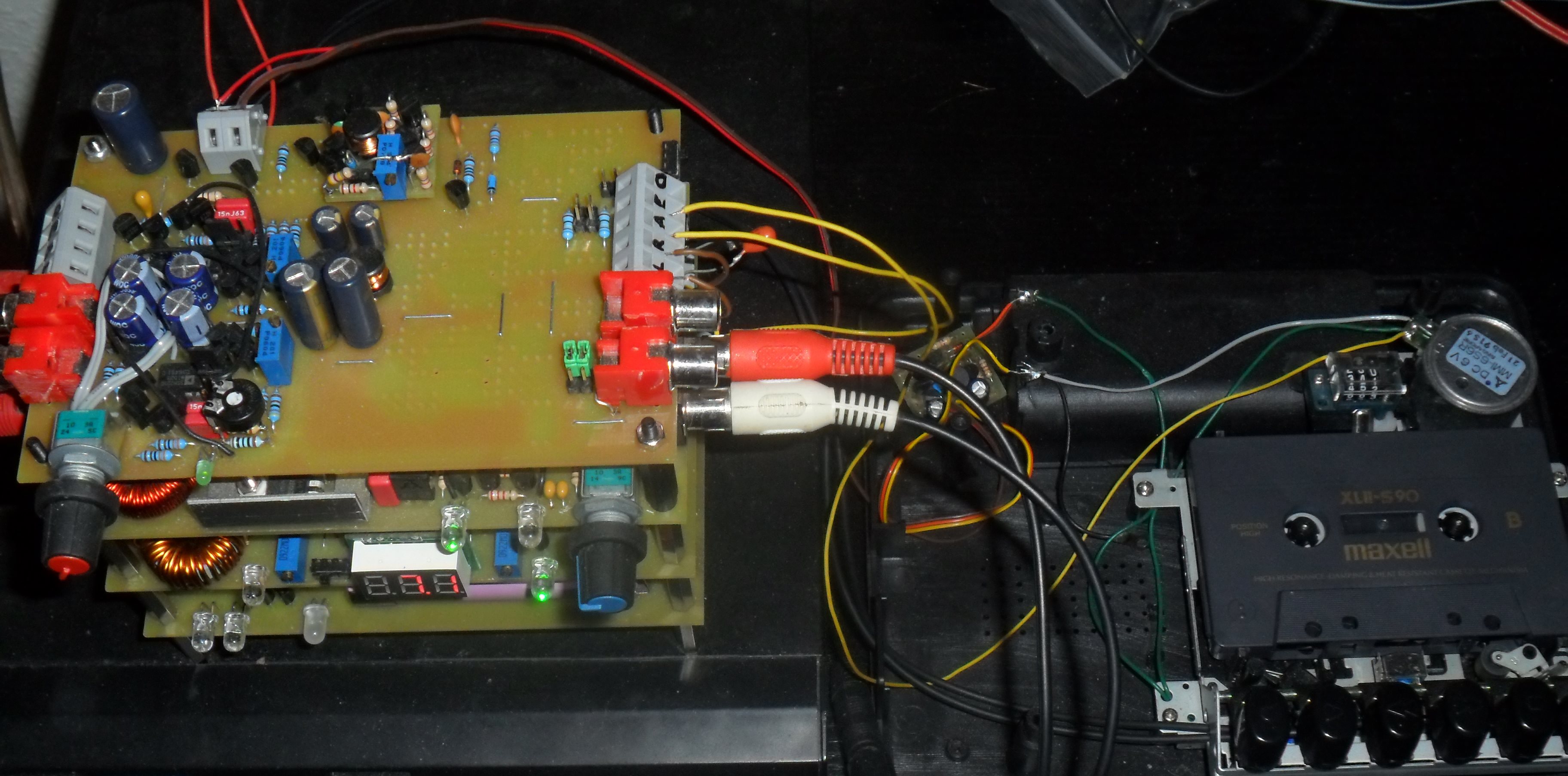
Now that my Stack has grown bigger with the preamp-module, I decided to get some visual presentation of the Sound”. A LED-Bargraph for the RMS power with peak-hold would be nice!

I also planned to build a discrete logarithmic volume switch and found that it’s best to integrate both functions on one module as both need digital control.

First I researched the famous LM3915 IC only to conclude that a pure hardware approach is to limited and inflexible. I thought that a common Atmega-Micropocessor should have more than enough power to implement these functions and maybe some more later on.

The Display-Module had already been designed in autumn last year: An Active Bicolor-Led Display Module of 7 x 40 Points:

BiColorMatrix

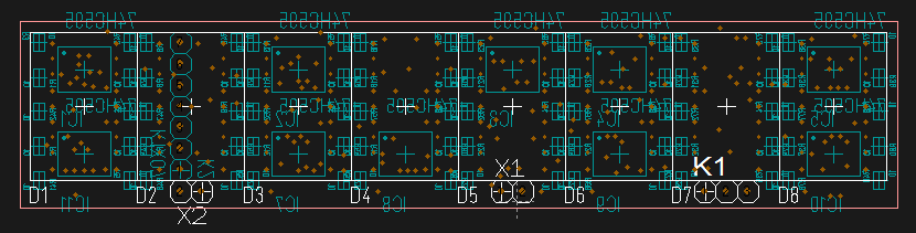
I has eight 5×7 matrices of the smallest size of 20mm height (OEM). As it is not possible to route 2 times 40 pins for the rows to external connectors, I needed to mount ten (!) 74HC595 shift registers in SSOP-package on the backside of the PCB. The craziness of this endeavour became clear to me as I needed 2 weeks to get the high-complex layout finished on a 2-layer PCB.

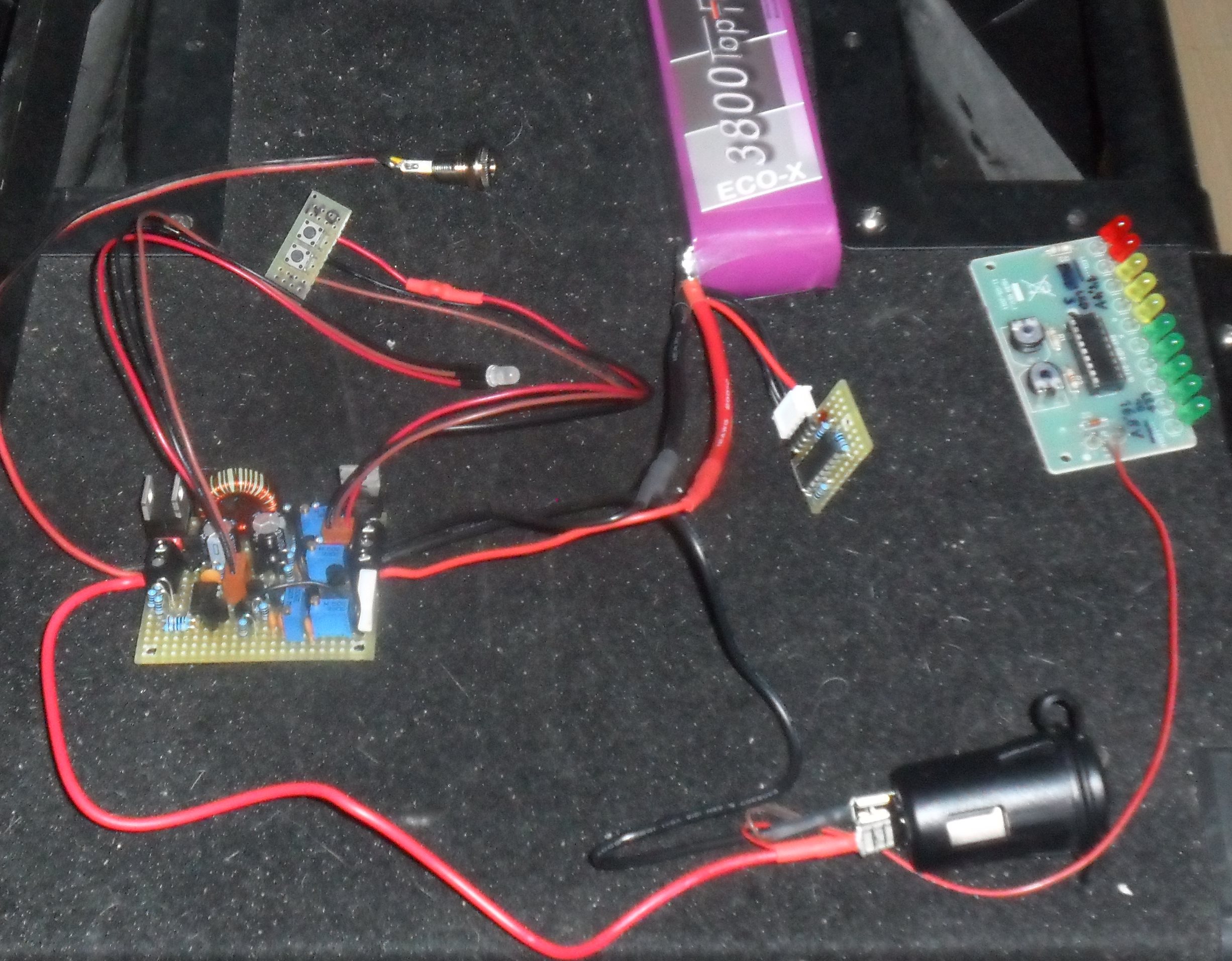
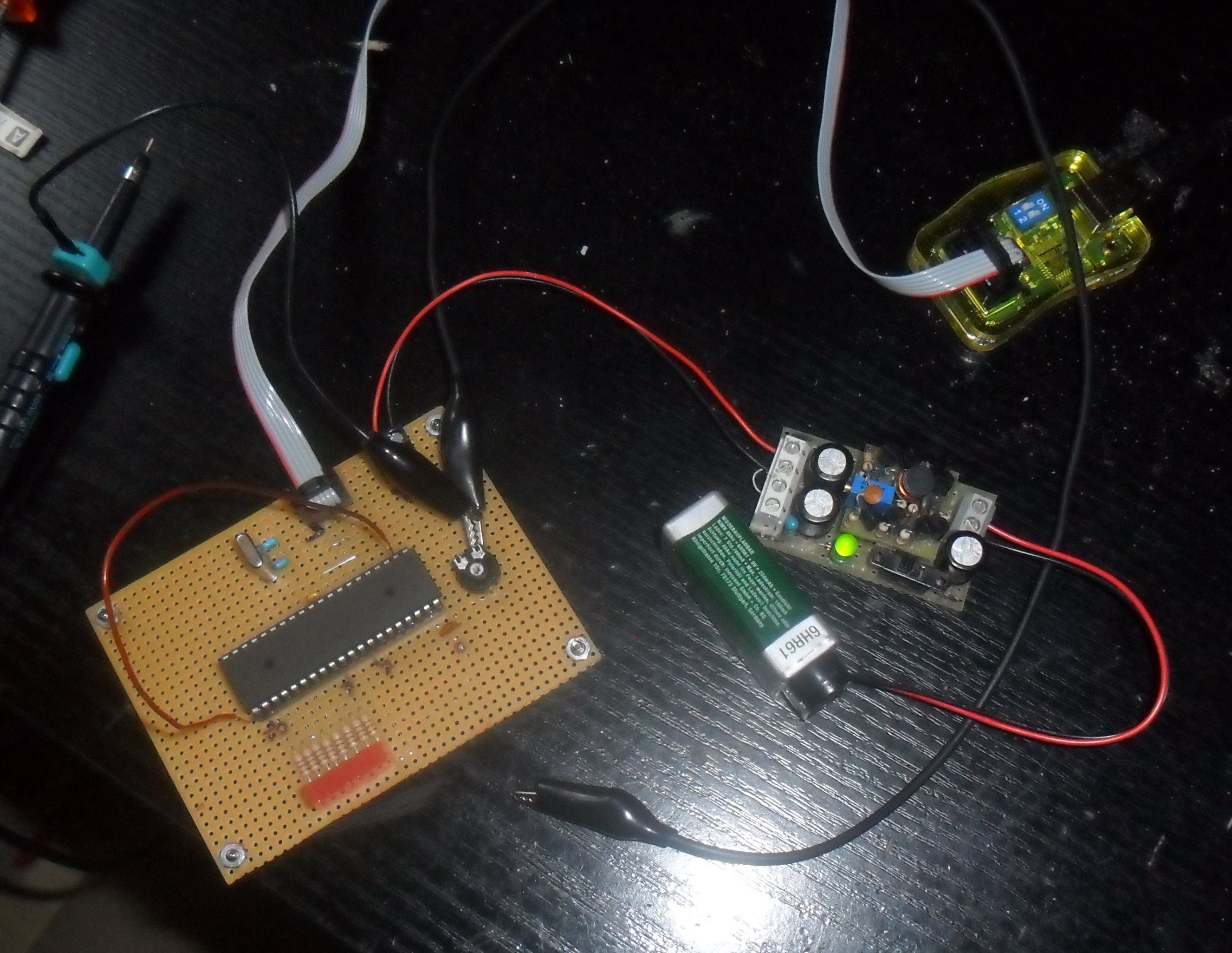
So it was now time to begin my first programming of AVRs. After the 2 Atmega32 and AVR-Progrmamer, that i have ordered, arrived, I build a small development board and wrote my first lines of AVR-Code in C.

SAM_0029

4 weeks later I had acquired some very interesting Insights into AVR-Programming:

  • Don’t try to push the ADC-Clock beyond 1 MHz with changing channel every time if you don’t have a sufficient break between the conversions. Otherwise the cross-channel isolation can be lost completely due to the big time-constant of the Switch- and S/H-capacitators.
  • You can’t do a true and fast Root-Mean-Square calculation on an 8-bit uP. Instead I had to satisfy myself with a averaged rectified Signal. For this I implemented a 10Hz-lowpass filter using a 256-Sample Ring-Buffer.
  • All the available ports are occupied by the Special I/O-Pins. It is not possible to avoid port extenders!
  • ISR’s need an incredible amount of time!
  • Processing Power is running scarce!!!
    I already had to decrease the samplerate down to 2*32kHz (Stereo muxed) to get the calculation done without any line written for the display control yet. I used an available Portpin to visualize the time needed for every single Interrupt (Image follows…)

Can AVRs be overclocked?!

A Lithium-Power Charger Circuit on the fly…

A good friend of mine called one day and asked me if I could build him a Li-Po Charger. His Girlfriend wanted to go hiking for some time and needed a way to accumulate solar power for her electronic gadgets.

So I designed and build the circuit in just a few days, though I needed about 3 weeks for it as my free time was a little low.

SAM_0018

Measuring of voltage and current is done with the help of TL431 Precision References, wired as PID-regulators, and tied to a Switched Buck Regulator for high efficency. I also implemented an electronic switch for shut-off with integrated discharge and under-voltage protection.

The whole assembly found its way into a plastic cycling-bottle, so it can easily be mounted on a bike:

(Image following!)


Transconductance Preamp

After I have designed my Line Transceiver, i wondered how much gain these kind of circuits can achieve. My aim was to build a discrete preamp that has:

  • High Forward Gain without any feedback loop
  • High Bandwith
  • Low noise
  • and of course with an Current Output Driver

During my experiments i had to learn the hard way what temperature coefficient does mean. Surpassing 20dB of Gain makes the circuit extreme sensitive to any change of the surrounding air temperature. The DC-Operating point of my circuits swinged across the whole range only by blowing some air over it! So at least it was necessary to implement a DC-Feedback path to compensates the temperature drifts. The graphic below show the circuit in simplified form:

mpppre

The Preamp is now build for a maximum gain of 86dB, sufficient for tape cassette replay.
The base-voltages at the Inputs lie about 2 Volts below the operating point due to the high input current and the 1 megaohms resistors. This has the advantage that the cascode stage (not shown here) can be tied directly to ground. The pot between the input transistors controll the sensivity of the Input stage. A higher impedance permit higher Input signals without raised distortions!

The passive EQ network can be adopted for all kind of equalizing curves, like reel-to-reel tape machines, vinyl players and others…

The following Image shows my implementations for the MPP-Stack. It uses one of my Switched Micro-Power Supplies to generate the necessary bipolar voltage of +/- 5 Volts. The free space on the right  is the recording amplifier that has not been mounted yet.

SAM_0030

In the picture you can see it connected with a disassembled cassette tapedeck. But I also have used it to digitize some Vinyl records…