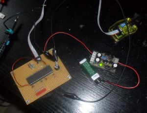
Now that my Stack has grown bigger with the preamp-module, I decided to get some visual presentation of the Sound”. A LED-Bargraph for the RMS power with peak-hold would be nice!
I also planned to build a discrete logarithmic volume switch and found that it’s best to integrate both functions on one module as both need digital control.
First I researched the famous LM3915 IC only to conclude that a pure hardware approach is to limited and inflexible. I thought that a common Atmega-Micropocessor should have more than enough power to implement these functions and maybe some more later on.
The Display-Module had already been designed in autumn last year: An Active Bicolor-Led Display Module of 7 x 40 Points:
I has eight 5×7 matrices of the smallest size of 20mm height (OEM). As it is not possible to route 2 times 40 pins for the rows to external connectors, I needed to mount ten (!) 74HC595 shift registers in SSOP-package on the backside of the PCB. The craziness of this endeavour became clear to me as I needed 2 weeks to get the high-complex layout finished on a 2-layer PCB.
So it was now time to begin my first programming of AVRs. After the 2 Atmega32 and AVR-Progrmamer, that i have ordered, arrived, I build a small development board and wrote my first lines of AVR-Code in C.
4 weeks later I had acquired some very interesting Insights into AVR-Programming:
- Don’t try to push the ADC-Clock beyond 1 MHz with changing channel every time if you don’t have a sufficient break between the conversions. Otherwise the cross-channel isolation can be lost completely due to the big time-constant of the Switch- and S/H-capacitators.
- You can’t do a true and fast Root-Mean-Square calculation on an 8-bit uP. Instead I had to satisfy myself with a averaged rectified Signal. For this I implemented a 10Hz-lowpass filter using a 256-Sample Ring-Buffer.
- All the available ports are occupied by the Special I/O-Pins. It is not possible to avoid port extenders!
- ISR’s need an incredible amount of time!
- Processing Power is running scarce!!!
I already had to decrease the samplerate down to 2*32kHz (Stereo muxed) to get the calculation done without any line written for the display control yet. I used an available Portpin to visualize the time needed for every single Interrupt (Image follows…)
Can AVRs be overclocked?!


I am glad to found your blog and read your article, very informative. Especially about Li-Po Charger… absolutely loved your this page. thank you for share