Tape recording take two

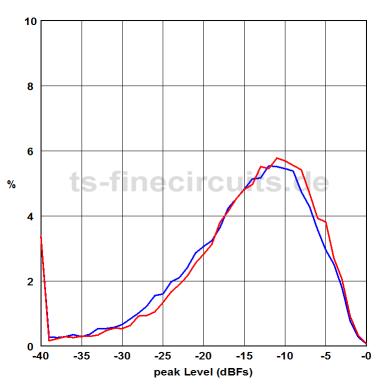
My first tests with the recording amp on my module and also research showed that you need about 0.5 mA peak for signal mixed with another 0.5 mA peak bias for some profound recorded audio.

Measurement at various tape heads showed an inductance of ~125 mH and ~100 Ohm ESR.

So at 1 kHz you need about 1 Volt for 1 mAmps…
at 10 kHz that makes 10 Volts…
and for the 100 kHz that makes 100 Volts!
-> What was I thinking?

Normally this is done using some transformer coils, or Toko coils as they’re named. Problem is that these cannot be found anywhere. There are various Toko coils to be found on the net but up until now I have not found one with the correct values and especially winding ratio to generate the high voltage bias signal.

So I don’t have appropriate coils, but I do have a few samples of a new fancy semiconductor:
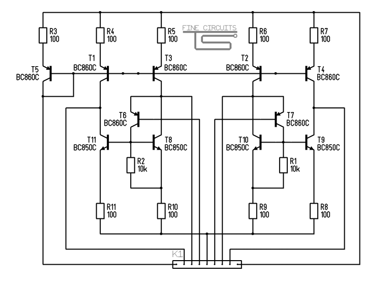
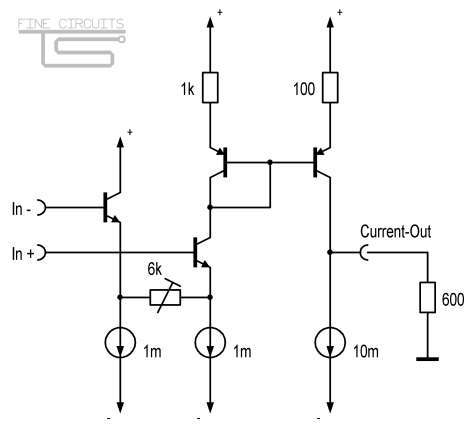
Depletion mode FET withstanding 500 Volts LND150. So let’s build a head feeding stage without coils:

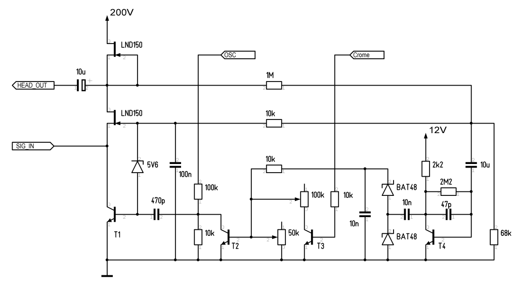
The upper FET acts as current source, the lower one as voltage shifter that fixes the input voltage to about 6 Volts. Of course I’ll feed pure current into it using my Dota-Sims.

T1 controls the sinking current and regulates the output DC voltage to about 100 Volts. It also adds the bias signal.

T4 has  a double task: it sucks out any LF out of the DC-Feedback loop and amplifies and rectifies it to control the bias level. Look it up at the datasheet of uPC1297 “Dolby HX Pro” controller 😉

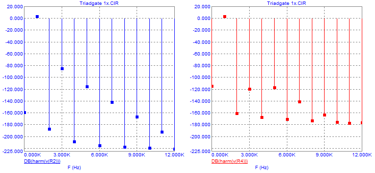
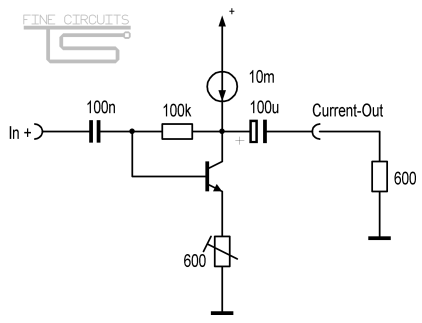
Simulation looks good so far, hoping to get some first results in at least another year…

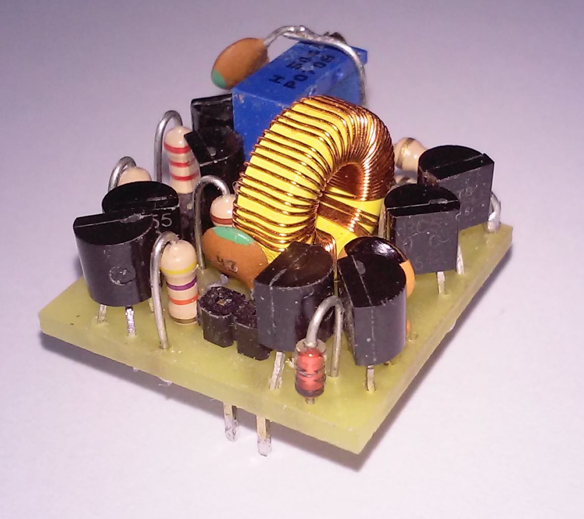
Of course I’ll need a 200V supply but that should not pose a problem with my mini switched converters.

Tenor TE7022L Evaluation

Several years ago I had the idea of obtaining an Interface USB Stick for SPDIF output and Input. I wanted to equip my audio stack with a codec for playback and record alike and optical fiber wire is just a cool way to transfer the signals as it also provide an absolute galvanic isolation.

There are hundreds if not thousands of kits and modules available that provide an output via this chip, but none could be found that provides an HD capable input path. So if it does not exist I gonna have to do it myself (and maybe this gonna be my first seller ;).

The chip is from the Galactic Far East Cooperation and they don’t provide very much of info beside the minimum datasheet for basic wiring. Nothing about the settings, config tools or if it’ll need an eeprom. The only way is to get a few and try it. Yesterday was the day to finally know if it works or if I blew 50 € into the wind. Here’s my evaluation circuit:

Result: It Works!
But not out of the box as the standard windows driver does not support Audio Class 2.0. Though I could select 24 bits resolution, the sample rate could not be set higher than 48kHz. After Hours I found a driver package that installs it as TeraDak X2 link and it also provides a control applet that let it switch to 24/96 for playback and record:

The driver was found here: teradak.com/download/2
If not available here’s my local copy: TeralinkX2.zip

I do not yet know if it really can do playback and record at 24/96 at the same time as I’ve read that this exceeds the 12mbps of USB 1.1 ?! Let’s see…

I looped back the output into the Input, started a singal generator and analsyed the input – or tried to as I could not start the record device in 24/96. So I went for 16/96 and got a dithered signal but at least without signs of resampling. Then I set the analzer to grab the samples in 24bit (the device still at 16bit) and got a clean signal, but the lower 8 bit were zeroed. That means that the Chip correctly receives the 24bit stream and the driver delivers at 24bit, but the transmission over the usb Interface back into the pc is cropped to 16bit!

So I’m now hoping to get an answer from GFEC for support or the whole project is doomed for failure and the ICs where bought in vain 🙁

Maybe I’ll try the Bravo SA9023 that shall be pin compatible next.

Transconductance as SIM (Single In-Line Module)

Life kept me occupied more than a whole year. Can’t believe that it’s so long since I last wrote something….

I decided to finally proceed on building a line receiver and transmitter module for my MPS-Stack. And of course it will be transconductance again!

The work for the digital module got stalled when I lost myself in the I2C-programming. Additionally I need that module there too for the digital volume control.

The receiver must be able to accept differential signals. I could use an OPA660/860 for that, but the transmitter shall have an differential output current and an OPA660 cannot do that. I could use two OPA660s or use an OPA2662, but given it’s rather limited supply voltage range and its limited flexibility I decided to keep my do-it-yourself notion.

I chose to mimic the pinout of the old NJM4558 SIP ICs,

only that mine will have an additional 9th pin for setting the bias current. For layout reasons I put it on the left end to become Pin “0”, so the numbering shifted one to the left. Following the complete circuit:

With a nice circuit twist for the input transistors (T6 & T7), that got inspired from John Broskie’s Triadtron I could improve the performance quite some bit:

– Higher input impedance
– Lower bias-to-signal ratio. I could reduce it from 7:1 to 3:1 while keeping the distortions below 0.005 %

The module will be mounted with SMDs. I gonna append pics of the first prototype, hoping that this will not take another 6 months…

… yeah, it took nearly one year:


Addendum concerning the distortions:

I discovered the main connection between the current ratios and the possibility for the distortion of the input and output stage to cancel each other out! The main variable in the circuit diagram above is the bypass resistor R1 and R2 that defines the bias current for the input stage. If its ratio to the transistor currents is set identical to the bias to signal current the distortion of the second stage fall far below the ones of the first stage. In number:

  • Peak signal current of 1.5mA, which results from 0 dbm or 0.7 Vrms into 600 Ohms
  • Bias current of just 3mA, giving a ratio of 2:1
  • Setting the resistor to 27kOhm results into 25uA through the resistor and about 12uA through the bases of the current mirror calculates the following hamronics:

Left: distortion after Input (R9, R10) Right: total distortion at output impedance of 600 Ohms

The total distortion at the output falls below 0.00015%


Switched Micro-Power Supply

In this Article I present my Switched Voltage Converter for the low-power range.

For example it can be mounted on a small PCB with 3 pins that can easily replace regular 78XX regulators. That will become the “simple” Version.

20160509_132248

The advanced Version in the image above has some quite impressive features:

  • The nominal output current is 250 mA, which is half of what the simple version can produce due to design reasons.
  • The module is absolutly overload and short-circuit proof.
  • In contrast to the simple version it can Buck and boost the voltage at the same time. The input and output Voltages range from 3V to 35V.
  • The negative output can even create a negative Voltage, though it must be stabilised with an externel Zener Diode.
  • Provides Control Pins for Enable Input and Power-OK Output

And the most important ones, and the reasons why I designed this Discrete Converter is:

  • The Design can be changed and adapted for high voltages using appropriate transistors.
  • The polarity of all semiconductors can be swapped with the opposite ones (NPN to PNP) to build the same converter for negative voltages!

For size reasons there are no output caps onboard and therefore the converter rely on external ones, like 3-pin regulators do too. These are mandatory, starting the circuit without them will immediately destroy it as the stored energy in the coil will induce extreme voltages. (Maybe I’ll fix that in an upcoming smd version of this converter)

I have already used two of these in my MPS-Stack. For example in my Preamp-Module it generates a very stable bipolar supply voltage of + and – 5 Volts independent of the Input Voltage that can be anything from 4 to 35 Volts.


Transconductance Preamp v2

My First Preamp has proofed its quality now for over a year. As I now plan to upgrade my record player with an integrated one, I worked on a improved and simplified version of my first prototype.

I already had the idea for this when my first version wasn’t even built, but I needed some time for basic design evaluation and performance simulation.

The most important change was to get rid of the bipolar supply voltage and a fast self-biasing upon startup while maintaining a low cutoff frequency. Waiting for more than 30 seconds until it gets operational while generating a loud “Plob” was not okay. Luckily I had an brilliant idea how to bypass this problem.

Of course it will again have an High-Z Current output that must be terminated with the proper 620 Ohms.

Here is the simplified schematic for Version 2 of my Transconductance Preamp:

Preamp Unipolar

Over the Xmas holidays I had enough time to solder the new prototype, it fits nicely into a corner of my Pioneer Record Player:

20160509_130209

I am going digital…

Now that my Stack has grown bigger with the preamp-module, I decided to get some visual presentation of the Sound”. A LED-Bargraph for the RMS power with peak-hold would be nice!

I also planned to build a discrete logarithmic volume switch and found that it’s best to integrate both functions on one module as both need digital control.

First I researched the famous LM3915 IC only to conclude that a pure hardware approach is to limited and inflexible. I thought that a common Atmega-Micropocessor should have more than enough power to implement these functions and maybe some more later on.

The Display-Module had already been designed in autumn last year: An Active Bicolor-Led Display Module of 7 x 40 Points:

BiColorMatrix

I has eight 5×7 matrices of the smallest size of 20mm height (OEM). As it is not possible to route 2 times 40 pins for the rows to external connectors, I needed to mount ten (!) 74HC595 shift registers in SSOP-package on the backside of the PCB. The craziness of this endeavour became clear to me as I needed 2 weeks to get the high-complex layout finished on a 2-layer PCB.

So it was now time to begin my first programming of AVRs. After the 2 Atmega32 and AVR-Progrmamer, that i have ordered, arrived, I build a small development board and wrote my first lines of AVR-Code in C.

SAM_0029

4 weeks later I had acquired some very interesting Insights into AVR-Programming:

  • Don’t try to push the ADC-Clock beyond 1 MHz with changing channel every time if you don’t have a sufficient break between the conversions. Otherwise the cross-channel isolation can be lost completely due to the big time-constant of the Switch- and S/H-capacitators.
  • You can’t do a true and fast Root-Mean-Square calculation on an 8-bit uP. Instead I had to satisfy myself with a averaged rectified Signal. For this I implemented a 10Hz-lowpass filter using a 256-Sample Ring-Buffer.
  • All the available ports are occupied by the Special I/O-Pins. It is not possible to avoid port extenders!
  • ISR’s need an incredible amount of time!
  • Processing Power is running scarce!!!
    I already had to decrease the samplerate down to 2*32kHz (Stereo muxed) to get the calculation done without any line written for the display control yet. I used an available Portpin to visualize the time needed for every single Interrupt (Image follows…)

Can AVRs be overclocked?!

A Lithium-Power Charger Circuit on the fly…

A good friend of mine called one day and asked me if I could build him a Li-Po Charger. His Girlfriend wanted to go hiking for some time and needed a way to accumulate solar power for her electronic gadgets.

So I designed and build the circuit in just a few days, though I needed about 3 weeks for it as my free time was a little low.

SAM_0018

Measuring of voltage and current is done with the help of TL431 Precision References, wired as PID-regulators, and tied to a Switched Buck Regulator for high efficency. I also implemented an electronic switch for shut-off with integrated discharge and under-voltage protection.

The whole assembly found its way into a plastic cycling-bottle, so it can easily be mounted on a bike:

(Image following!)


Transconductance Preamp

After I have designed my Line Transceiver, i wondered how much gain these kind of circuits can achieve. My aim was to build a discrete preamp that has:

  • High Forward Gain without any feedback loop
  • High Bandwith
  • Low noise
  • and of course with an Current Output Driver

During my experiments i had to learn the hard way what temperature coefficient does mean. Surpassing 20dB of Gain makes the circuit extreme sensitive to any change of the surrounding air temperature. The DC-Operating point of my circuits swinged across the whole range only by blowing some air over it! So at least it was necessary to implement a DC-Feedback path to compensates the temperature drifts. The graphic below show the circuit in simplified form:

mpppre

The Preamp is now build for a maximum gain of 86dB, sufficient for tape cassette replay.
The base-voltages at the Inputs lie about 2 Volts below the operating point due to the high input current and the 1 megaohms resistors. This has the advantage that the cascode stage (not shown here) can be tied directly to ground. The pot between the input transistors controll the sensivity of the Input stage. A higher impedance permit higher Input signals without raised distortions!

The passive EQ network can be adopted for all kind of equalizing curves, like reel-to-reel tape machines, vinyl players and others…

The following Image shows my implementations for the MPP-Stack. It uses one of my Switched Micro-Power Supplies to generate the necessary bipolar voltage of +/- 5 Volts. The free space on the right  is the recording amplifier that has not been mounted yet.

SAM_0030

In the picture you can see it connected with a disassembled cassette tapedeck. But I also have used it to digitize some Vinyl records…


Discrete Transconductance Line Transceiver

After all my experiences with buidling switched ampliufiers, i felt the need to venture into the field of discrete analog circuits. I’ve read a lot about guys on the net that still today, in the time of ICs, build Opamps out of discrete parts.

They say because it sounds better,
it provides more flexibility, and higher bandwidths.
They say that feedback loops should be avoided at all.
Listening via an OpAmp is like watching an orchestra through a key-hole!

I was researching circuits to convert an symmetrical input into a non-symmetrical one avoiding the classic OpAmp circuit all together. Trying to think like one of these audiophile maniacs I thought that a 4-resistor bridge does no “feel” very good: in regard to the floating reference levels, and especially the limited input impedance against ground.

On  the other side are memories of frustating tries to eliminate the ground hum between amp stages, weather for recording sound from the tv-set or wiring multiple amplifiers on partys that draw their power from different sockets.

One way that this can be avoided is by using symmetrical or at least quasi symmetrical signal Transmission.
Another way can be found by force-feeding pure current through the line:

I’ve got the idea that you can have XLR-like quality on standard lines when the receiver does not perceive any noise voltage that can occur along the cable. This can be achieved by transmitting current instead of voltage, as long as the correct terminating impedance is kept maintained, like f.e. 600 Ohms.

This is the result:
mpplxc

All you’ve got to do is buffering the input into an defined impedance and mirroring the resulting current into the output line. Just have a look on the performance:
• THD: < 0.01 % (can be improved by raising bias current)
• -3dB Bandwidth: 6.5 MHz
• Slew Rate: 200 V ⁄ μs
• Output Impedance: 440 kOhm

For simple unipolar signals there is an even more simple way to build a current driving output; just take a self-biasing transistor with an current source as pullup:
c-out

This is a cheap way to upgrade your stereo with an current line-out, won’t cost more than using an OpAmp as output buffer!

Loudness Scan

Do you hate brick-walled music? Do you hate over-compressed sound?

Me Too!

Surfing the web about the development of Music Mastering, like the Loudness War on Wikipedia, I stumbled over Jim’s Audio page about HDCDs, where a tool was used that analyses the loudness spectrum of audio files.

I just had digitalized some LP recordings using my new Transconductance Preamp when I thought it would be a nice idea to get this Dynamic Plot for the recordings so I can compare it against other albums. Unluckily I had to find out that the original program was not able to handle larger files, so with the help of the original source code from Keith Howard I was able to code my own console-app called “Loudness Scan” and a tool to generate the corresponding emf graphics:

LSshot Jethro Tull - Minstrel In The Gallery

The images show the Volume Spectrum of my digitized recording of “Jethro Tull – Minstrel in the Gallery”. A Spectrum like it should be. The spike at the lower end contain all values below -40dB.

Link to the file:
LoudnessScan.zip

This is the first Version of the tool, only for analysing 2 x 16bit Wave-files. The png-write is not (yet) implemented and there are some bugs with rendering the emf inside emfexplorer… But for now it does what I wanted it to do.